Part 2 is here.
This week I worked on making a 3D printing a geared wheel hub drive for a Keda 190KV brushless motor. I designed it in Designspark Mechanical.
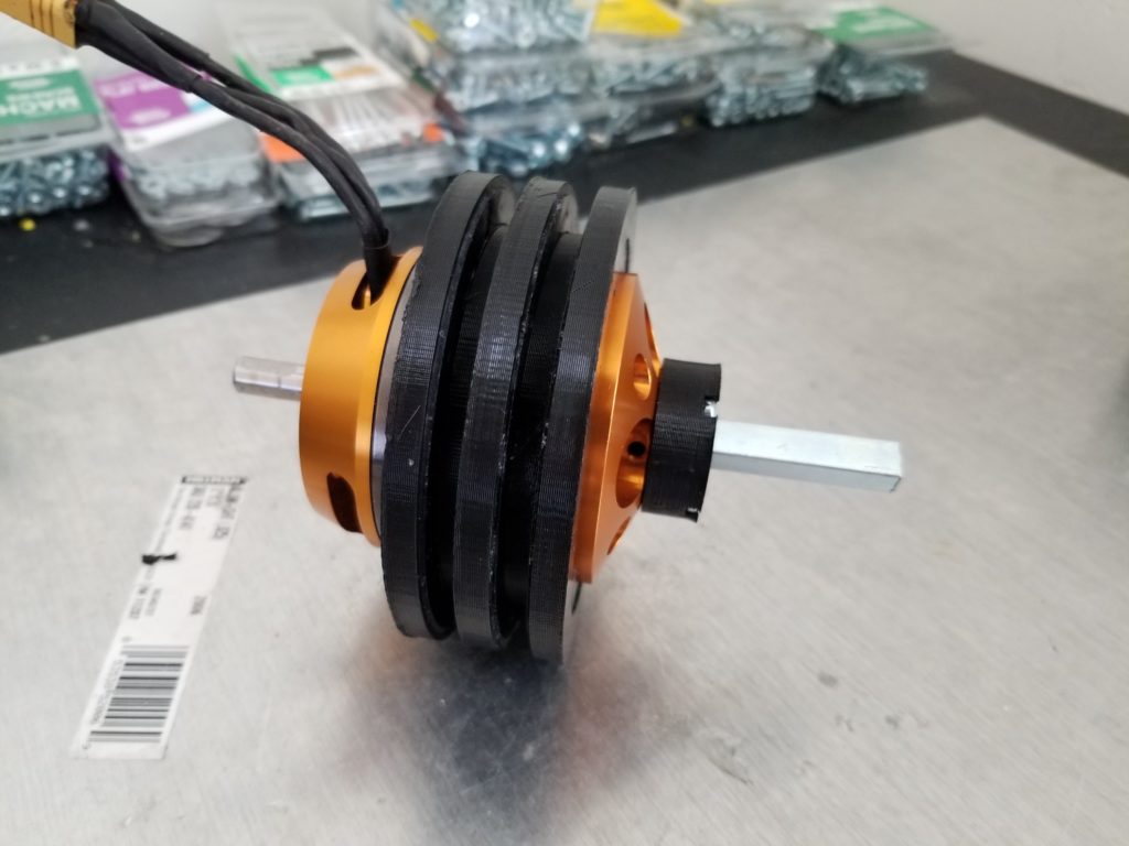
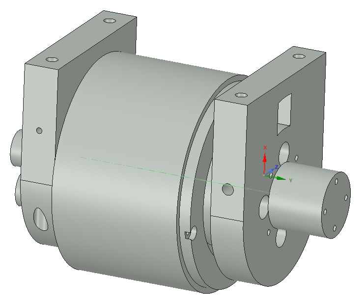
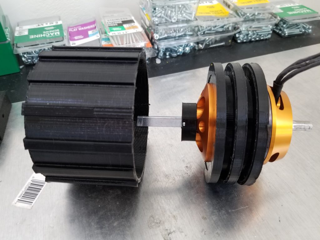
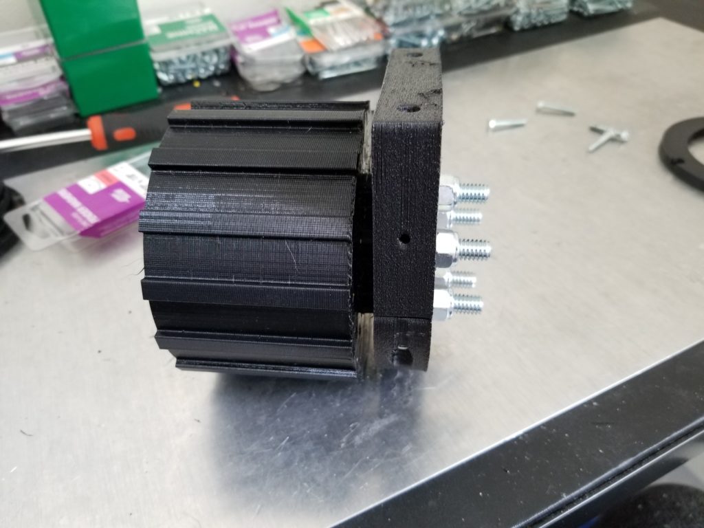
Figure 2: 3 bearings going around the motor and attachment for the rear shaft
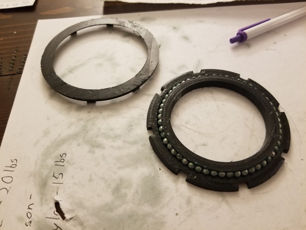
First I designed bearings that go around the motor. The motor is an outrunner, so the outside spins when the motor is powered on. 3 of them are pushed onto the motor, as shown above. I also 3D printed 2 spacers to keep the bearings from moving. Also shown below is the attachment I made that screws into the rear of the motor. A 5/16″ square rod is inserted into the attachment.
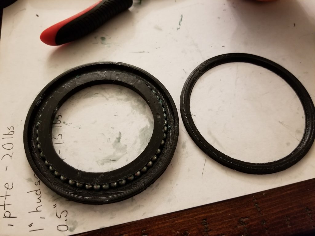
Shown above is one of bearings. The bearing is made with 4.5mm BBs. The cap (on the right) is glued in. I used Loctite Super Glue Gel Control and Gorrilla Super Glue Gel Control. Both seemed to work very well.
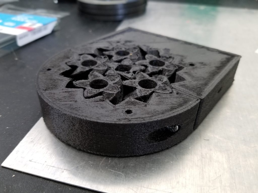
The other end of the square shaft is inserted into the sun gear of a planetary gear, shown above. The gear was modified from this design by emmett on Thingiverse. With his design, you normally print the ring, planets, and sun gears all at once. The parts will be slightly fused together, so you need to break them apart by forcing the sun gear to turn. Instead, I broke the ring gear into 2 pieces so that I could print each part separately and then assemble them.
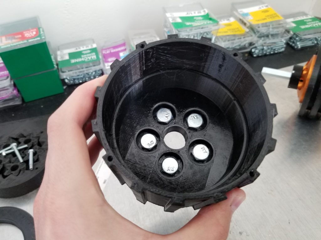
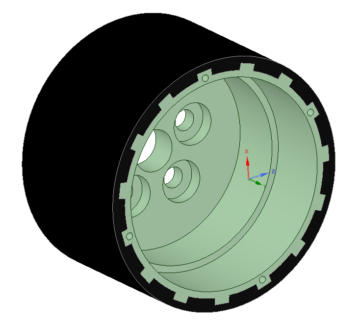
Shown above is the Y carriage that attaches to the planetary gear. 5 bolts are going through it. The bolts are what will attach the Y carriage to the planet gears.
The motor and bearings go inside of the Y carriage (or hub I guess you’d call it?), as shown below.
I printed some spacers that go on the bolts, shown above.
Shown above the Y carriage is attached to the planetary gear. I used nylon nuts to secure it. The nuts are screwed down just enough to prevent the bolts from wiggling around as the gear spins, but not enough to cause extra friction.
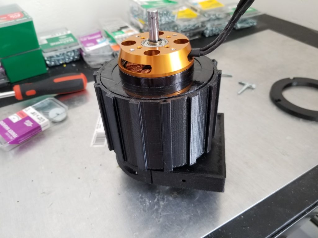
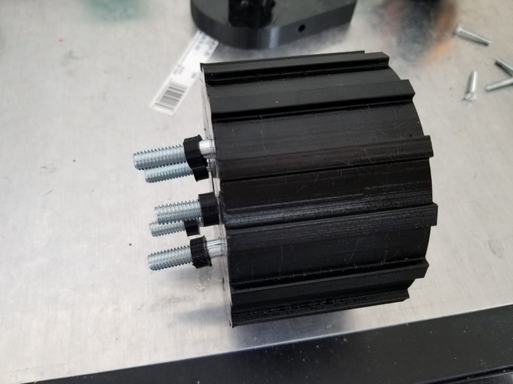
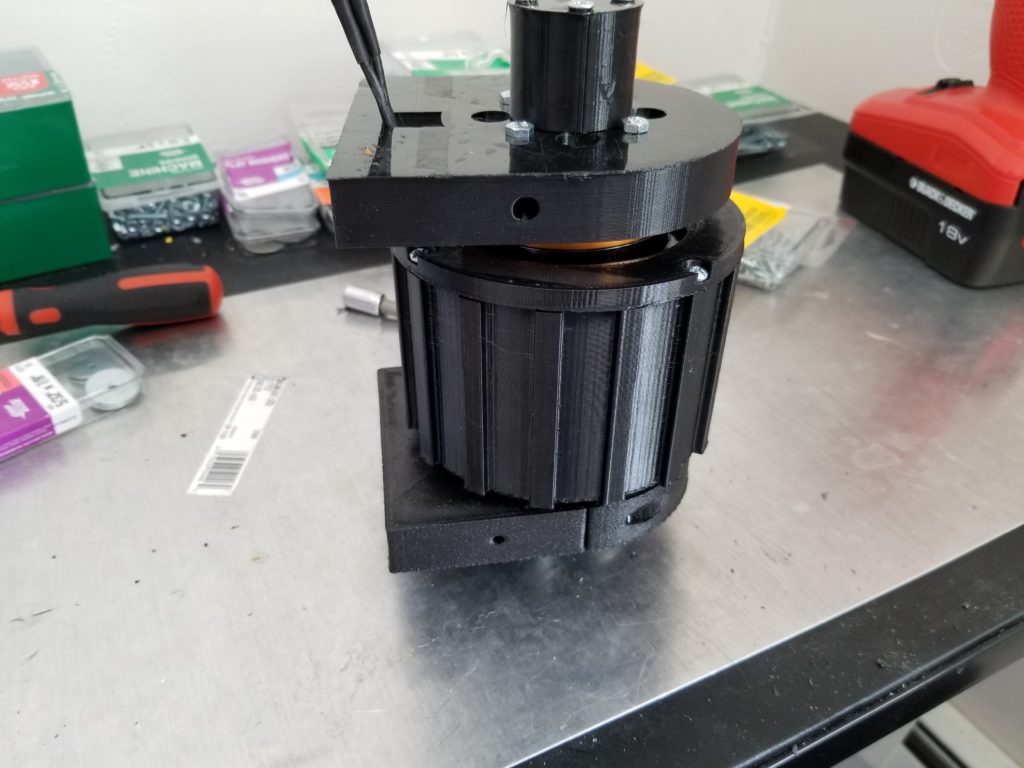
Shown above, the motor and bearings shown in Figure 1 are inserted into the Y carriage hub.
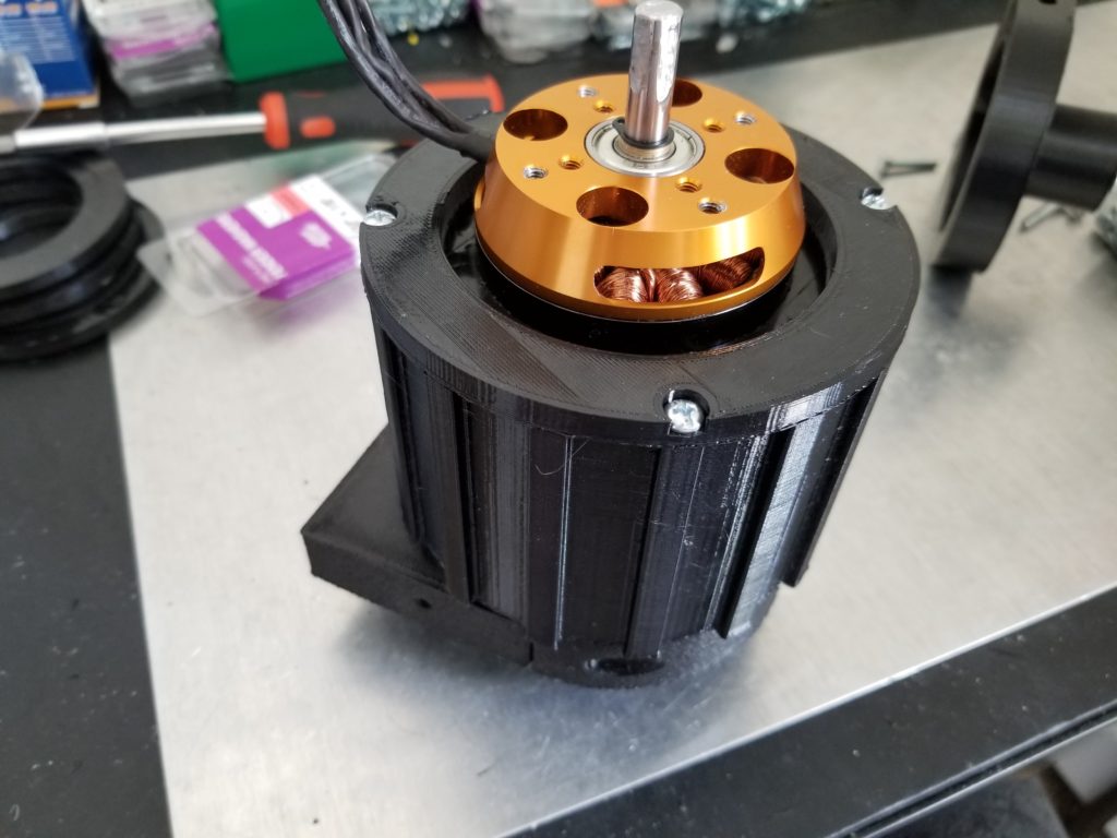
Next, I made a cap that fits over the other end of the Y carriage hub to keep the bearings from coming out.
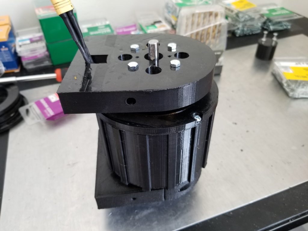
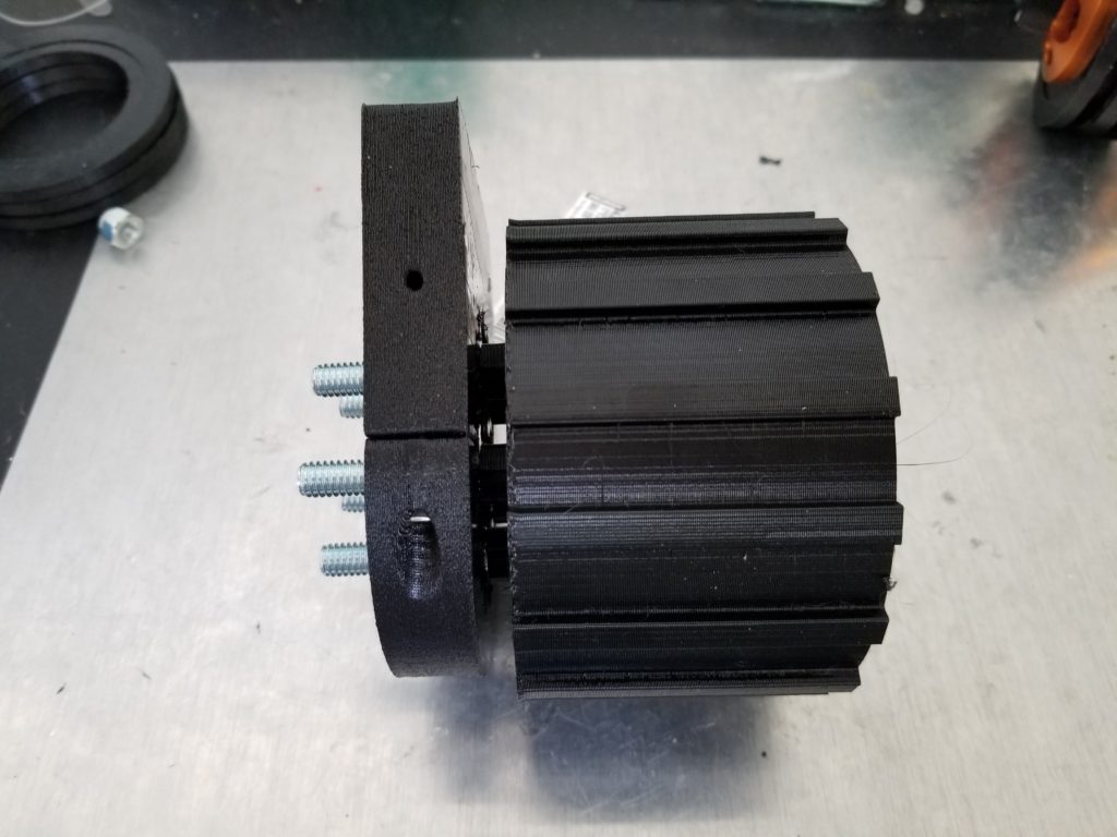
Shown above, I mounted a piece to the front of motor.
Finally, I made a cap that fits over the shaft of the motor.
Shown above is my first test of the wheel hub drive. You can see when I zoom in on the planetary gear that the sun gear is spinning faster (4 times faster) than the planet gears and the Y carriage. This is the gearing that I wanted to achieve.
Since I didn’t need it for testing, I didn’t print the tire that will fit around the Y carriage hub yet, shown above in black.
Improvements
There are several improvements that I’d like to make to the wheel hub drive. First, the planetary gear was printed with too small of a tolerance. The ring, planet, and sun gears fit together too tightly making them hard to turn. The gears are generated using an OpenSCAD file and the tolerance is one of the parameters. Increasing the tolerance should solve this issue.
Second, I’m going to replace the spacers shown in Figure 7 with metal washers instead. I believe washers will have less friction and better handle the heat generated by the turning.
Third, I believe I only need 1 bearing, not 3 as shown in Figure 2. I would only leave 1 bearing on the end to support Y carriage hub. With only one bearing, there will be less friction. However, I’m worried that if I take the middle bearing out, the Y carriage hub will strain under the weight I plan to put it under. To help, I’m going to try to redesign the Y carriage hub so that I can reinforce it with at least 8 1/4″ steel rods.
Fourth, and finally, I’m going to see if I can make the bearings shown in Figure 2 without using glue. Even though the glue seemed to work very well, I’m worried that it will degrade over time. I tried to redesign them to use snap-fit joints instead, as shown below.
However, they didn’t seem to work too well. I may try to make the snap-fit joints work, but right now I’m thinking that I might be able to use zip ties instead.
I will make these improvements and then post the results in part 2. If I’m happy with the results, I will upload the 3D model files to Thingiverse. Stay tuned!