I have moved my VR Shoe content to this site. Please go there to learn about it. I’ve left the content here just for historical value.
I’m making motorized shoes to be used with virtual reality games. The shoes keep you in the same spot as you walk, like a treadmill. You can walk infinitely in the game while staying in the same spot in the real world. The shoes are omni-directional so you can turn, strafe, and walk in any direction.
- Current design
- First test
- Return to center algorithm
- How much power does it use?
- This looks dangerous
- Safety Structure
- Is crouching supported?
- Is running supported?
- These don’t look very stable/responsive
- How will you improve stability and responsiveness?
- Is jumping supported?
- How much does it cost?
- How do the components communicate (wifi, bluetooth)?
- How will these interface with a VR headset?
- What about omni-treadmills?
- What about macanum wheels?
- Will these work on carpet?
- How will you reduce the noise?
- Will you sell these?
- What’s your business plan?
- Will you get a patent?
- Google has a patent
- Are you worried about your idea getting stolen?
- Will you license your idea to a company?
- How can I contribute?
- Are you looking for business partners?
- Donations?
- Where can I follow you?
- Other versions of the shoes
- How heavy are these?
- What are your goals with this project?
- What if I don’t want to/cannot install a ceiling mount?
Current Design
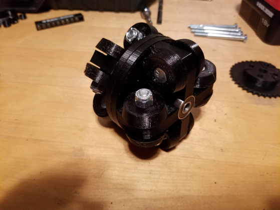
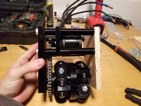
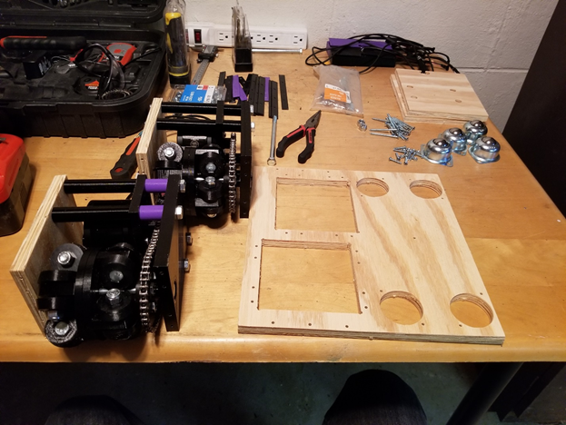
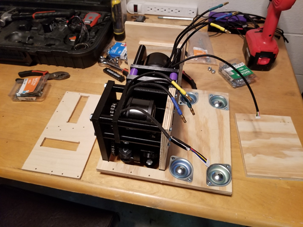
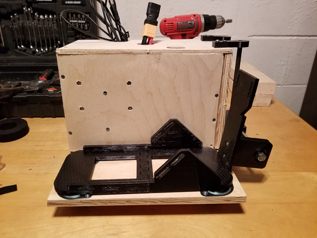
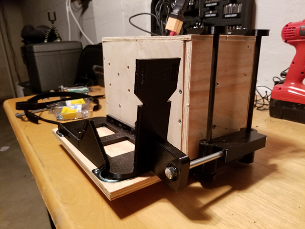
The current design uses omni-directional wheels mounted to the bottom of a platform.

It uses 50mm Rotacaster Omni-directional wheels. One set of wheels are for forward/backward motion, the other is for sideways motion. They are coupled to two Flipsky 270KV motors. Two VESCs are controlling the motors. Currently I’m using an Arduino Uno Wifi Rev2 to control the VESCs, but I plan on switching to an ESP32 very soon. I’m using an 5AH lipo battery to power each shoe. Most of the parts are 3D printed.
The way the user’s foot is coupled to the platform is shown above. The binding, as I call it, rids along two rods up and down and can pivot in the center. The binding allows the user to lift his foot up like he normally would while walking. The rest of the shoe follows the user’s foot along the ground. This means the user does not have to lift the whole shoe, which is heavy. Instead the user just has to roll the shoe along the ground, which feels much lighter than actually lifting the shoe.
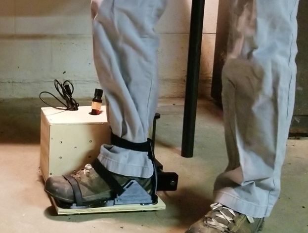
Lastly, these are intended to always be used with a safety harness secured to the ceiling or to some sort of safety structure. These are basically roller skates you where with your eyes covered up (by a VR headset), and without a safety structure the user could get hurt.
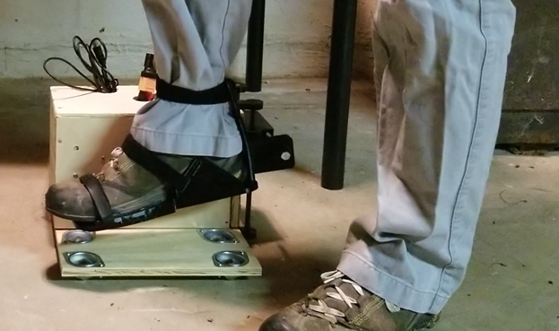
First Test
Above are the first tests I did with this design. The shoes were barely ready for a test like this. They used a very basic algorithm, manual controls, and not-great electronics. I did not expect them to be very responsive or stable at this point. Still, for the very first tests, they worked well. I am working on improving their stability and responsiveness.
Return to center and braking algorithm
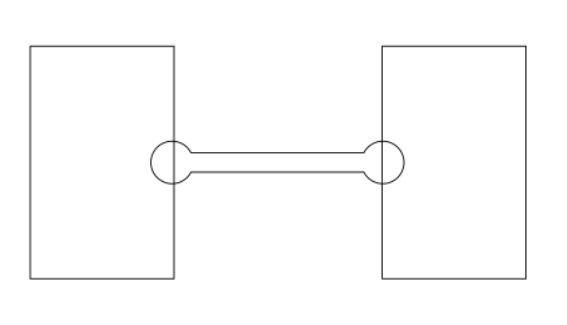
In my first tests, I manually controlled these with my phone. How am I going to automate them? I explained the algorithm in part 1, but there are a few more details I need to add. Please refer to the following image.
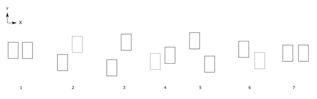
When the rectangle is solid, that means that the user’s foot is on the motorized shoe. When a rectangle is dotted, that signifies that the user’s foot is in the air and the user is bringing the shoe forward (or to the side) along with their foot.
Step 1 is the starting position of the user, where they are standing still, shoulder-width apart. In step 2, the user starts taking a step forward. The right foot is in the air, and the motorized shoe is being brought forward along with the user’s foot. The sensor in the right shoe will detect an acceleration in the positive Y direction. The acceleration in the positive Y direction in the right shoe will trigger the left shoe’s main motor to turn on. The left shoe will be start moving backwards at the same speed the right shoe is moving forwards. The speed to use can be calculated by using the accelerometer data (integrating to get the velocity) or by using motor encoders. So put in other words, When the user takes a step forward with his right foot, the left foot is moved at the same speed in the opposite direction.
In step 3, the user has put their right foot down on the motorized shoe again. In step 4, the user lifts their left foot and begins moving it forward. Just like in step 2, when motion is detected in the left foot, the right foot’s shoe will start bring the right foot back at equal speed in the opposite direction.
In step 5, the user has brought their left foot down. Now the user decides to take one last shorter step, and then to stop. The shorter step is shown in step 6. In step 7, when the user brings their right foot down, she does not start to move their left foot. Since she doesn’t move their left foot, no motion in the left foot is detected, so the motors in the right foot’s shoe do not start up.
Let’s now imagine that in step 5, instead of the user taking another step forward, she decides to take a step to the side, as shown in figure 12.
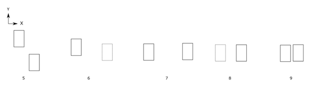
Shown in step 6, the user will lift their right foot and start moving it in the positive X direction. In step 7, the user has put their right foot down. In step 8, she continues their strafing to the right. She brings their left foot up and starts moving it I the positive X direction. Since motion in the left shoe is detected, the right shoe will start moving sideways in the opposite direction. In step 9, the user brings their left foot down.
An additional thing to consider with strafing and that I think I’ll need to incorporate into the algorithm is that, with strafing, the user’s feet should not crisscross. If the user lifts his right foot and moves it X distance to the right, the right foot’s shoe should not move back a distance greater than X.
Braking must also be considered in this algorithm. When the user is standing still, the motors should lock the wheels in place so that the user feels like he has stable footing. When the user is walking, for example, straight forward, the motor in charge of moving side to side will hold its position so that the shoe does not move to either side when it’s supposed to only move straight backwards. To detect the user lifting his feet, buttons will be on the top of the platform. When the buttons are compressed, the user’s foot is on the platform.
The algorithm, step by step, is as follows.
- When the user is standing still with both feet on the platforms, the motors should resist any motion.
- When the user lifts one of his feet to start walking, his foot will come off the platform. That will be detected by the buttons on the platform. This will cause that shoe’s motors to stop holding their position.
- A 2D vector will be constructed that indicates the direction and speed the user is moving his foot and the shoe in.
- The other shoe, where motion is not detected and the user has not lifted his foot, will have its motors activated so that the motorized shoe starts to move. It will move at the same speed as the other shoe, but in the opposite direction.
- When the user brings his foot that was in the air down, the buttons will be compressed. The distance the shoe moved will be stored.
- When the user starts to lift his other foot, the same process will occur. The shoe for the foot that is still on the ground will move in the opposite direction with the same speed. If the user is strafing, the shoe will not move more than the stored distance.
- When the user stops moving his foot that is in the air, or bring his foot down and does not continue to move it, the motors in both shoes will be stopped and they will hold their position again.
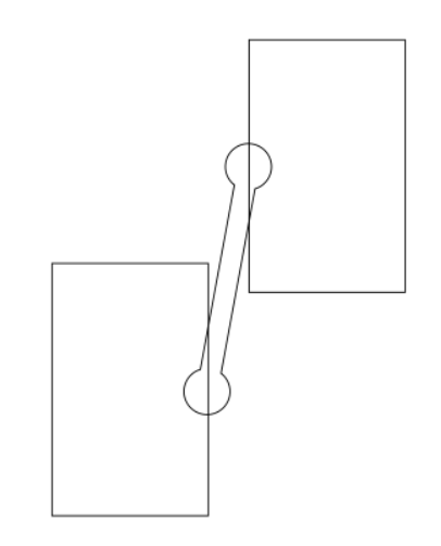
What I have just described is what I call the return to center algorithm. In addition, another sensor can be used to bring the user to the center. Please refer to the following image.
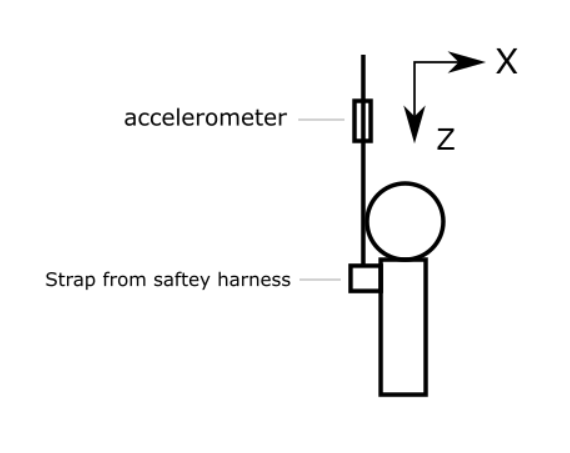
Modern day accelerometer can measure acceleration in 3 or more directions, including the acceleration due to gravity. In the above image, the accelerometer will detect the acceleration due to gravity in the Z direction. The X and Y directions will not feel any acceleration due to gravity. Using the detected acceleration due to gravity, a 3D vector can be constructed. In this case, the X and Y components of the vector are 0, and the Z component is 9.8 (assuming the accelerometer reports acceleration in meters per second per second).
If the user takes a step forward, then the accelerometer will detect this because the Z axis will detect less of a pull due to gravity, and the X direction will start to feel a pull due to gravity, as shown in below.
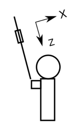
Another 3D vector can be constructed. The X component could be 4 and the Z component could be 7, for example. If the user then takes a step directly left or right (relative to their point of view), the Y component will feel a pull due to gravity. Then the Y component could also be 4, for example. Then the 3D vector will be (4, 4, 7). Using this vector, the direction the user is away from the center point can be measured. The exact distance the user is away from the center point cannot be precisely measured unless the height the accelerometer is from the ground is known, but knowing the exact distance is not necessary.
Using the sensor in safety harness tether, the direction to move the shoes such that the user returns to his starting position can be calculated.
Please note that I am considering using a safety harness tether that uses a rigid rod that will not allow the user to take a step away from his starting position. If I go that route than an IMU in the tether will not be needed. It’s also possible that the return to center algorithm will be good enough and a sensor in the tether will not be needed in any case.
Also note that this algorithm does not rely on detecting how close the user gets to a physical boundary, like a wall or furniture or boundary sensor. It relies on detecting the direction and speed of the user’s feet and their position relative to their center point.
Also, I may find that for some people, when they are walking it would feel more natural if the motorized shoe assembly would move the user’s foot back at a slightly different velocity than the velocity of the foot moving forward.
To accomplish this, I can create a separate small device that the user straps onto their shoe. This device will contain an accelerometer or gyro. This device is used separate from all of the other components, meaning she is not strapped into the safety harness or the motorized shoe assembly. When the user activates the device, she can walk forward, backwards, side to side as much as she wants. She should do this in an open area so that she has enough room to walk in every direction. While the user walks, the device will collect the accelerations of the user’s feet. This data can then be used in the algorithm to slightly adjust the speeds at which the motorized shoes move so that it feels more natural for that user.
How much power do these use?
I’m not sure exactly yet. I need to do more testing. I did testing with these for about 30 minutes and I guess that it could last an hour or maybe an hour and a half (draining the lipo battery to a safe amount). But I was just walking. Running and a heavier user will use more power.
One thing to keep in mind is that with every step the user takes, the battery is recharged a little. When the user lifts his foot to take a step forward, the platform is moved along the ground. The wheels spin and backdrive the motor, turning the motor into a generator and recharging the battery. This recharging with every step can greatly increase the time before recharging the battery with a charger is needed.
If power requirements are too high, I will consider not powering these with batteries but instead with a power supply that plugs into the wall.
This look dangerous
I try to make this as clear as possible in the videos and all my posts – these are intended to always be used with a safety harness. The safety harness should be secured to the ceiling to prevent the user from falling and moving away from his starting position. Or it should be secured to a safety structure that is strong and stable enough to prevent the user from falling.
Safety Structure Designs
My current safety structure setup is simple, a safety harness coupled via a chain to a swivel hook secured to a stud in the ceiling. This structure is simple.
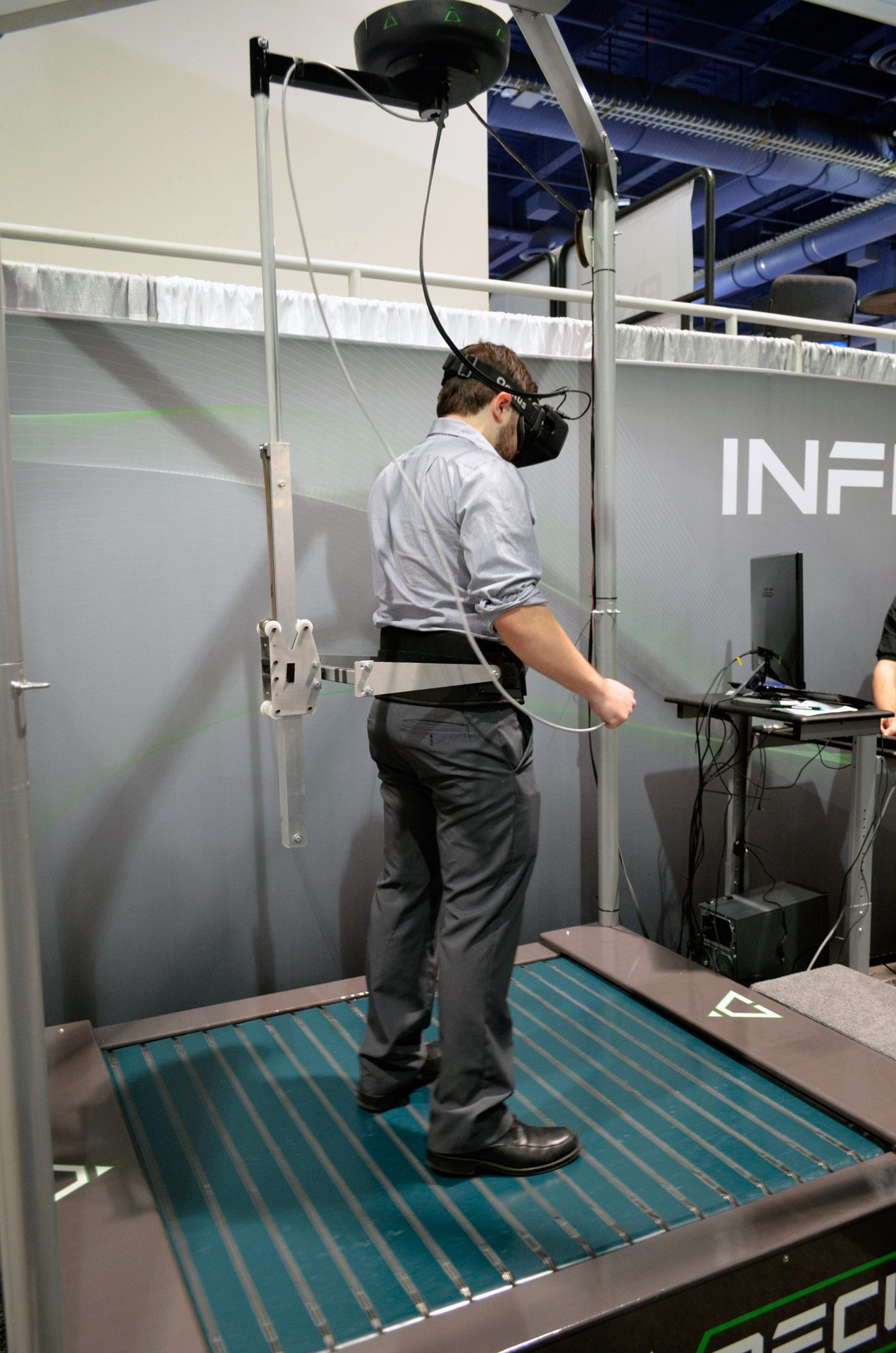
However, I’m going to try to improve the structure to help increase stability. I want to have support for the user around the user’s waist. I want the safety harness to be coupled to a rigid rod or beam that extends down from the ceiling. This is similar to the safety structure that the Kat Walk and Infinadeck use.

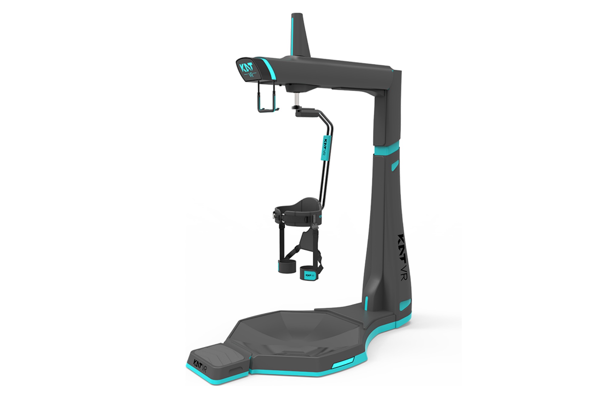
So what I want to do is have a hook in the ceiling that can rotate which is attached to a rigid rod, with that rigid rod attached at the user’s waist. I can also couple the existing buckle in my safety harness to the rod for more safety. I have an idea of how I can set this up and I’ll be trying it in the next month or two. I think it will provide a lot of stability while at the same time not feeling restrictive. Later on I can also modify it to support crouching.
Crouching support can be added by having the rigid rod that extends from the user’s waist to the ceiling actually consist of two rods that can slide against each other a short distance, along with a spring to pull the lower rod back up when the user is not crouching.
Will crouching be supported?
I plan on supporting crouching in the future. I plan on redoing the safety structure I have in place to support crouching while still keeping the user safe. Please see the safety structure designs section for more details.
Will running be supported?
I’m focusing on support walking right now. I want to support jogging speed, but I don’t think these will support a full out sprint. Maybe if the components could be made from metal instead of plastic and maybe if I could fit shocks into the shoes. It’ll be something I’ll look into in the future.
These don’t look stable/responsive
I have just shown my very first test so far. The shoes were barely ready for such a test. They were using a basic braking algorithm and I was manually controlling them with my phone. I also was using an Arduino Uno to control each shoe, which I found out is not fast enough. Given all that, I did not expect these to be very stable and responsive in the first test, and neither should you.
I will be improving the stability and responsiveness in the coming few months. Please see this section for details on what improvements I will make.
How will you improve stability and responsiveness?
First, I’m going to get better electronics.
I’ve been using an Arduino Uno Wifi Rev2 as the micro controller for the shoes. I’ve found that the wifi is slow, most of the time taking at least 20ms to fully parse a http request. It also only has one hardware UART, which can support up to a 115200 baud rate. Since I have 2 VESCs, one gets the hardware UART, the other gets a SoftwareSerial, which can only reliably use a 38400 baud rate. I want faster baud rates to speed up the algorithm.
I’m going to replace the Arduino with an ESP32. It looks like the wifi is faster on it. It’s dual core, so I can have two threads running at the same time. It has 3 hardware UARTS. It’s maximum UART baud rate is 5000000. It also has bluetooth, like the Arduino did.
Next, I’m going to improve the algorithm. I will automate the shoes, please see this section if you would like to know the details on the algorithm I’m going to use. I am also going to implement PID loops for starting up and braking the motors that can be calibrated based on the user’s weight.
I am also going to improve the safety structure to improve more stability. You can read more details here.
Will jumping be supported?
I’m early on in the prototyping, so I’m just focusing on walking, turning, and strafing. I don’t think full jumping will be supported with these shoes, unless I can make all the plastic parts out of metal (not something I am capable of with my current equipment) and/or implement shocks.
As a substitute for jumping, I think something that can work is to have the user lift his heels up off of the platform, keeping the balls of his feet on the platform, to simulate a jump. So quickly lift your heels to jump in the game. To achieve this, I could use the buttons on the top of the platform. I can have a button under the ball of the foot and one under the heel. If the buttons under the balls are pressed but the ones under the heels aren’t, that’s a jump.
How much will these cost?
Take a look at the BOMs that I have in the github repository. For the prototype, I’m using powerful motors and ESCs, used normally in electric skateboards, so they’re expensive. These powerful components are great for prototyping because I don’t have to worry about quality and power.
The prototype version I’m working on how has a BOM that comes out to about $1200. I have another BOM in the respository where I think I can get the cost down to $600. I also have an idea for another version of the shoe where I can bring the cost down further. Keep in mind the costs include the safety harness and ceiling bracket.
Please keep in mind that I don’t have the resources of a large company, where I can order large volumes of parts and drastically reduce the price. This is also a new, novel idea, and very new, novel products usually start out expensive. I’m also not focusing too much on cutting costs right now. I want to get a fully functional prototype working first.
How will these communicate with each other, the headset, and a PC?
I want to support wifi and bluetooth communication between all components.
How will these interface with a VR headset?
I’m going to implement a SteamVR driver that communicates with the shoes and translates the events from the shoes to SteamVR events.
For native Oculus Quest support, I’m considering having each shoe emulate one of the Oculus Touch controllers. Shoe 1 will pair with touch controller 1, shoe 2 will pair with touch controller 2. Each shoe will provide all the services that the touch controllers provide. The Oculus Quest app will pair with each shoe, thinking each shoe is a touch controller. All output from the touch controllers will go to the shoes, then the shoes pass that onto the app, except the shoes can override movement.
What about omni-treadmills and other VR locomotion solutions?
There are other good solutions to the VR locomotion problem. There are omni-treadmills like the Virtuix Omni, Kat Walk, and Infinadeck. There are also sensors that you strap to your feet and you run in place to run in the game, like the Kat Loco. There are also the CyberShoes.
VR treadmills that rely on a slick surface, like the Virtuix Omni and Kat Walk, are simpler. They’re basically just a slippery bowl that you slide in. The Infinadeck is more complicated, consisting of a conveyor belt of conveyor belts.
VR treadmills are large and heavy (more than 100 pounds). Shipping cost for these treadmills can be very expensive. According to a lot of people online, and a few people who have commented on my posts, the slick surface treadmills do not feel like walking. They feel like sliding on ice and overall are uncomfortable to use. With the Kat Walk C coming out hopefully we can get more opinions. Maybe it’s just something you get used to.
So the VR shoes are more complex, but VR treadmills are large and heavy. Most VR treadmills are also much more expensive. The slick surface treadmills might not feel comfortable. The VR shoes should feel like natural walking, cost less than $1000 (maybe much less), won’t have a huge shipping cost, are light and mobile and can be thrown in a closet when they’re not being used.
What about Mecanum Wheels?
A few people have suggested mecanum wheels. The reason I didn’t go with mecanum wheels is because you need a motor per wheel. So that’s 4 motors per shoe, 8 in total. Each motor will probably need gearing. 2 motors together have to be powerful enough to move the user. They also have more friction, because when you want to move sideways a couple of the wheels hold their position, so they’re creating some friction.
Will these work on carpet?
No, unless it’s very thin carpet. The omni-wheels I’m using are not designed to be used on carpet.
Can you reduce the noise?
I can try to use these on a very thin piece of carpet or rubber to reduce the noise. I might just use these with headphones on.
Will you sell these?
I hope I can. If I can make a version that is sellable, I’ll need to use them for at least a few months to see how well they last. I’ll also need to see if any manufacturers would be willing to help me produce these, or if I can produce them myself with a 3D printer farm. I’ll also need to look into any safety requirements that the VR shoes need to meet before I can sell them.
That being said, I may not be able to make these sellable. They might just be too expensive. Assuming I can get the BOM cost down to $600, I still need to increase the cost from there to cover all the other expenses that come with selling a product. I need to cover maintenance of my equipment, shipping (parts to me), pay myself, business taxes, packaging, etc. The COGS may be much higher than the BOM cost. Then businesses generally have to multiple the COGS by at least 2.5 to be able to stay in business, and even more to be a profitable business. The notion that, for example, the cost for materials for something costs $10 and you can sell it for $15 seems to be common and is completely false. With all that in mind, if the cost of the materials is $600, the retail price might be at least $1500. I don’t know if anyone is going to pay that much, so I might not try to sell these. Or maybe I’ll just sell the 3D printed parts. I’m not sure yet. It may be possible to get the cost down by getting lots of funding to invest into injection molding, volume orders, and even making parts overseas with cheap labor, but I do not want to go that route. It’s also possible that I could sell a cheaper version of the shoes instead that have reduced functionality.
What are your business plans?
My primary goal is to make something cool, useful, and share it with others. I think open-source is the best way to increase innovation. I do want to make some money and I’d be happy to make just enough money to support myself. I want to build a small business slowly on the side, at a reasonable pace, with low risk.
Right now, I am not looking to turn my life upside-down by trying to get a startup going. I have a good job that I enjoy, work-life balance, 100% remote, flex-hours, and good pay. I get to spend every night with my wife and have free time to relax and pursue my interests, like the VR shoes. I am happy where I am at with my life right now and I am not looking to dramatically change it.
There is this popular entrepreneur and hustle culture that pushes working incredibly hard and this narrative that everyone should be an entrepreneur, that becoming an entrepreneur means you can work when you want, on what you want, and be your own boss. You’re a loser if you work a regular job and are not constantly hustling.
I find the hustle and startup entrepreneur culture to be toxic and incredibly misleading. Running a startup is incredibly stressful. You do not choose when you work, you are working all the time. You do not get to be your own boss. Your clients and customers are your boss. You are very likely to fail. People will point to all the success stories anyone can find online, but they will not talk about the many, many, more people who did the same thing and failed. There is a huge amount of survivor bias in hustle culture.
You do not get to work on what you want. You need to wear many hats when you run a business. If you’re an engineer like me and like developing a product and you think you will enjoy running a business to sell your product, you may be wrong. You won’t be spending most of your time solving engineering problems that you enjoy. You will spend most of your time running the business. That means you will spend time doing marketing, accounting, legal, managing customers/employees/clients/investors, being a boss, and many running all the other aspects of your business. So even though you enjoy using your engineering skills to solve problems and make products, you might absolutely hate actually running a business to sell your products because most of your time will be spent running the business.
With all that said, I do not want to run a traditional startup. I would need to completely destroy the life I’m happy with now and replace it with an incredibly stressful, hectic life.
I plan on continuing to develop an open-source prototype while I build a YouTube channel. Assuming I can make a sellable version, I plan on using the version for a couple months to see how well they last. I need to look into any safety regulations I need to meet, and get product liability insurance. I can produce a small batch of DIY kits and sell them. If they sell well, I can get another 3D printer or two and continue producing small batches and continue to build a 3D printer farm. If demand is too high for me to keep up with using a 3D printer farm I can look into manufacturers and possibly launching a crowd funding campaign. With this approach I can scale slowly, be flexible, work my day job, and have very low risk.
If the VR shoes don’t work out I will still have a YouTube channel I can grow and a 3D printer farm I can use to make other products.
Are you going to get a patent?
No. This is open-source, a better way to increase innovation than patents. I do not have $10k to get a good patent. I do not plan on licensing this product to a company for a variety of reasons. A patent is not useful to me because I do not have the money to defend the patent.
This video sums up most the reasons I won’t be getting a patent. Again, patents do not prevent someone from making your product. You have to go after them, and you need the money to do so. Patent litigation can cost hundreds of thousands of dollars or millions.
Google has a patent!
First, Google does not have a patent. They have a patent application. It’s not a full patent yet, and the scope of the application will very likely be reduced or the application will be thrown out.
Second, even if the application becomes a patent, as it is now, my VR shoes do not infringe on any of the claims. If you’re unfamiliar with patents, the only thing that matters are the independent claims. Please look up how to evaluate a patent if you do not know how.
I am not a lawyer, so do not consider anything I say here to be legal advice.
Claim 1 doesn’t apply to my design because my design doesn’t have a flex region, or a linkage assembly. It also doesn’t use a belt.
Claims 2-11 are dependent on claim 1 so they don’t apply. I read through them anyway. None of them apply.
Claim 12 doesn’t apply because the physical position of my motorized shoes are not tracked. Mine does not detect a distance between the shoes and a physical boundary, no threshold distance is measured. The shoes are not actuated in response to any distance. In my design, the shoes actuate in response to each other’s direction and speed.
Claims 13-18 are dependent on 12 so they don’t apply.
Claim 19 is vague in my opinion, but it still doesn’t apply for the same reasons claim 1 and 12 don’t apply. Claim 19 is like a summary of claims 1 and 12, so I don’t really understand why it’s there.
Claim 20 is dependent on claim 19, so it doesn’t apply.
Are you worried about your idea getting stolen?
Kind of, but an idea alone isn’t worth much. I’m actually executing on it. I think it’s better to get the word out then to hide the idea. I feel we benefit more from sharing. Sure my pride will be hurt if some company takes the idea and makes millions, but I’ll be glad that I was able to help get a another solution to the VR locomotion problem to the general consumer.
Are you going to license your idea to a company?
No. It goes against my goal of making something useful and sharing it with everyone and I’m not getting a patent.
How can I contribute?
You can join the discord and make suggestions on how to improve the design, download the design file and make modifications, make the shoes yourself, help with coding (when it’s needed), share posts, or offer moral support. If you want to contribute in other ways let me know!
You can find the design files here.
Are you looking for business partners?
Not at this time and I don’t know if I will in the future.
Donations
You can donate here. Make sure to un-check goods and service so that there is no fee.
Where can I follow you?
Other future versions of the shoes
I’ve been thinking about an idea since the testing I did in in video #26. In it, I mentioned that the back swinging my leg naturally does when taking a step actually helps the shoes. The motion of the swing helps the shoes come backwards and the motors need to use less power. I found that with the power off, it’s still pretty easy for me to just swing my leg back and have the shoe come along. I’m wondering how much the active help the shoes gives you when your leg is swinging back is actually needed. If the shoes are low on friction, maybe actively helping the user isn’t needed. Or similarly imagine you just put on roller skates and start trying to walk in place (ignore the problem of keeping your balance, I’ll talk about that). This is sort of like the slippery surface omni treadmills today, where you’re just sliding along a slip surface and actively using your own power to bring your feet back. The problem is this feels like running on ice and I’m sure feels unnatural. From the reviews and hearsay I’ve found online, a lot of people who have actually used the slippery surface treadmills say it doesn’t feel natural and isn’t a great experience.
So I was thinking, in other words, is what if the shoes don’t need to actively help the user because the motion of the user’s swinging legs is powerful enough as long as the shoes are frictionless enough? The problem is I don’t want the shoes to feel like running on ice, like the slippery surface treadmills, and if there the shoes are free to move as they please it will be really hard for the user to balance. He’ll be sliding all over the place.
Here’s my idea. Maybe the shoes don’t need to actively help the user with motion, but what if they just have active braking? What if I could just actively brake the X and/or Y directions and provide gradual resistance? I think with active braking, it might not feel like running on ice, because the shoes will provide resistance and the appropriate times. And it should be easy for the user to maintain his balance since the shoes can prevent movement in directions the user doesn’t want to go.
Why do this? Because only having to supply active braking will make the shoes cheaper. If you take a look at the BOMs I have in the github repo now, the one for actively helping the user walk I estimate is around $600. I also have one there for only having active braking, and the cost goes down to about $400. I’d like this to be as cheap as possible, or at least have different versions. So maybe have the most expensive version be the one that actively helps with walking, then another version that just has active braking, then maybe even a cheaper version that isn’t omni-directional (just forward/backward, which will have severely reduced functionality). So my plan is to keep going with the current version, which is actively helping the user walk, but I’ll develop two algorithms. The first will be for actively helping the user walk. The second will just have active braking. I’ll switch back and forth and see how the two compare.
Another even cheaper version could be one that doesn’t use motors and just uses springs that wind up and provide resistance or assistance at certain times while the user walks.
How heavy are these?
Keep in mind that you’re not lifting these shoes off the ground. They roll along the ground, following your feet. Since they’re on wheels and you do not lift them, if friction is reduced enough they could feel weightless. The motors could also help move them to make them feel weightless. With that said, they’re about 10 points each, but to me they just feel like wearing boots. I haven’t added any code to make the motors assist and haven’t put any effort into reducing friction, but I will in the future.
What are your goals with this project?
- To make a solution to the VR locomotion problem that an individual can put together and easily source all the parts for.
- To innovate, share, and promote open-source, so that we can all benefit.
- To show how at home manufacturing with 3D printers can enable anyone to create useful, novel inventions. Home based manufacturing methods like 3D printing have enabled individuals to innovate and create things that, until recently, only companies could make.
- I want to be an example of an entrepreneur who made a successful small business without breaking the bank, maintaining a full time job, and maintaining a balanced life. I want to be a counterexample to entreporn and the toxic parts of hustle culture.
- To inspire others to make their own solutions to problems.
What if I don’t want to/cannot install a ceiling mount?
I plan on making something like the portable pull up bar stand below as an alternative to a ceiling mount. My version will need to be wider so that they user can reach out with his arms and not touch the structure and so that it will never tip over.
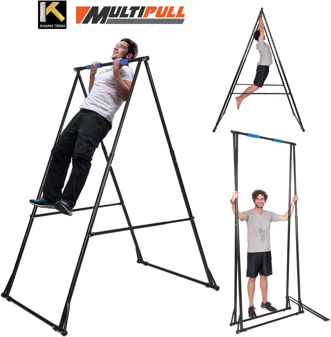
You can secure the safety harness to the top horizontal bar. When you’re not using the VR shoes, it can fold up, and I’ll make mine so that it can also get shorter, then you can store it in a closet. I’m planning on making this out of parts that anyone can get at a hardware store and easily build themselves (drilling into pipes might be needed, so anyone with a drill).
With this design it is still probably very possible for the user to pull the whole structure in some direction. I have several ideas to stop that from happening which I will try out in the future. The simplest is feet or material on the bottom of the structure that increase friction. Another idea is something like a support rod that will push against the ceiling and the structure. Another is to add the ability to secure this to a wall. Finally, another is to have the bottom of the structure coupled to a sheet of wood that the user stands on.
Edits:
August 5, 2020: Added other future versions of the shoes, how heavy are these, and what are your goals with this project sections.
August 14, 2020: Updated other versions section with an idea for a shoe that could use springs to wind up. Updated the cost section to say that the costs include the safety harness and ceiling bracket.
August 15, 2020: Added the ceiling mount alternatives section.
Expanded on how heavy are these section. Previously it was:
Keep in mind that you’re not lifting these shoes off the ground. They roll along the ground, following your feet. With that said, they’re about 10 points each, but to me they just feel like wearing boots.
August 21, 2020: Added more details to will I sell these section.