I have moved my VR Shoe content to this site. Please go there to learn about it. I’ve left the content here just for historical value.
Last Thursday, November 21, 2019 I posted this article that briefly talks about my virtual reality motorized shoe that I’ve been working on. I briefly describe it and link to my YouTube playlist build log series. I created the YouTube channel on November 14, 2019, and uploaded videos 1-4 in the series. In video #2 I talk in detail about the design, except for the binding component. The 5th video was uploaded on November 21, 2019, where I talk about the binding component in detail. I’m going to try to upload a new video about once a week.
I also made an Imgur post about the VR shoe on November 21, 2019, and it got an incredible amount of views and made it to the front page. As of today it has about 127k views.
In this post I would like to go into more detail about how the VR shoe works, including how the sensors and algorithm that tell the shoes what to do work.
Current Solutions
A problem with current virtual reality set ups is that you have to stand in one spot. If you walk forward, you will run into whatever is in front of you (a wall or physical object). To make the virtual reality experience more immersive, it would be ideal to be able to walk infinitely in the virtual world, in any direction, but stay in the same spot in the real world.
Solutions for this problem already exist; they are called omni-treadmills. Below are examples of omni-treadmills.
You can see that the first two consist of a platform that is slippery so that the user can slide her feet. The Infinadeck relies on conveyors. All of the treadmills are bulky, heavy, not available for purchase for the individual consumer, and from what I could find, very expensive. I also wonder how natural it feels to walk on a slippery surface and slide your feet back.
My Solution
At a high level, my idea is a motorized shoe that allows a person to walk while staying in the same physical location. Using this device and other VR equipment, a user can walk infinitely in a video game while staying in the same physical location in the real world.
Omni-treadmills are large and heavy contraptions, making them hard to move and store. My motorized shoes are lightweight and can easily be stored in a closet. My design will also have of a safety harness connected to a support structure or a hook in the ceiling to make sure the user does not fall over.
My Design
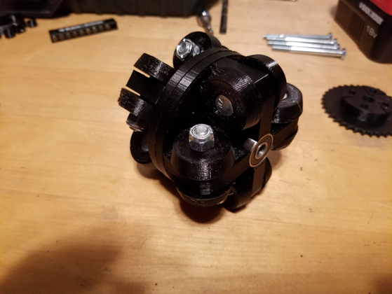
My design consists of a platform that is moved around by a pair of motors and a pair of omni-directional wheels. One omni-directional wheel is shown in Figure 1.
One omni-directional wheel is coupled to one motor via sprockets and a chain, as shown in Figure 2. A gear train or belt pulley system could also be used to couple them together.
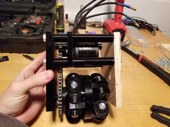
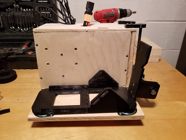
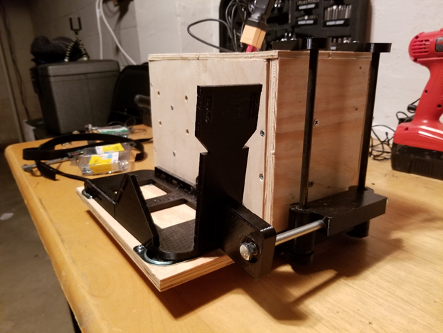
I call the component shown in Figure 2 a drive assembly. Two drive assemblies are coupled to a platform. Figure 3 shows the two drive assemblies and the platform.
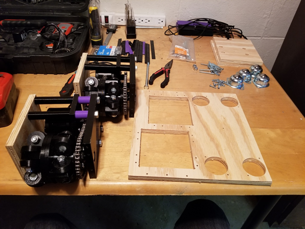
Figure 4 shows the drive assemblies coupled to the platform.
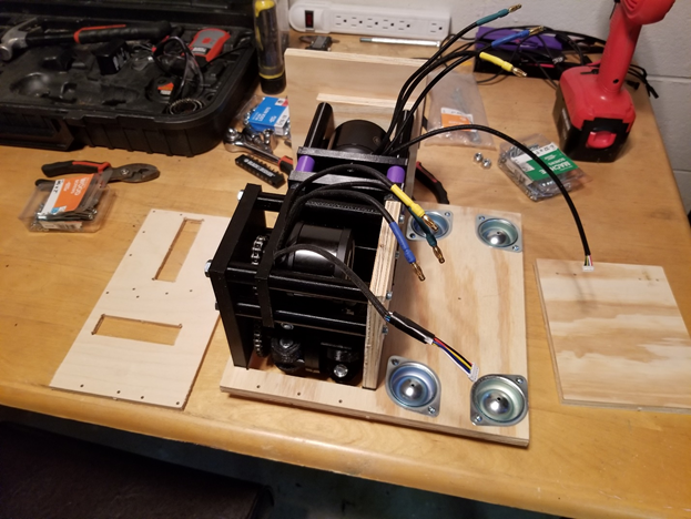
You can see that the drive assembly closest to the camera is coupled in one direction, and the drive assembly further away from the camera (partially obstructed from view) is coupled in 90 degrees off from the other drive assembly. This is so that the shoe can move in any direction when the motors are powered up. The drive assembly closest to the camera, when the motor is turned on and the wheel is acuated, will cause the shoe to move forward or backward. For the other drive assembly, when its motor is powered on and the wheel turns it will cause the shoe to move side to side. If both motors are powered on at the same time, the shoe will move at a 45 degree angle. If both motors are turned on and the motors rotate at different speeds, the shoe can be moved at other angles. So the shoe can move at any angle by controlling the motors turning on and off and controlling their speed.
If the shoe should not move, it can brake the motors to prevent the shoe from moving. For example, if the user is standing still, the motors will brake such that the wheels will not move and the shoe will resist moving in any direction. If the user is walking straight forward, then one drive assembly (the one closest to the camera) will actuate its wheel to move in the forward direction, while the other drive assembly will brake and have the wheel locked in place so that the shoe resists any movement from side to side.
These two short videos show a prototype of the shoe I built. The first video shows one drive assembly’s motor powered on so that it brings my foot backwards. The second video shows the other drive assembly’s motor powered on to bring my foot sideways.
https://i.imgur.com/jp2IBq4.mp4
https://i.imgur.com/wnFZ5c4.mp4
Figure 4 also shows 4 ball transfer units coupled to the platform. These ball transfers support the weight of the person. Ball transfers are ideal because they are small and allow movement in any direction. Casters could also be used, or any wheel/sphere that supports movement in any direction. Next, there is a component that straps to the user’s foot while keeping the user coupled to the shoe. This component allows the user to lift his foot while staying coupled to the shoe. The component is shown in Figure 5 and Figure 6.
The user will use straps to secure his foot to the binding (straps go through the rectangular holes), as shown in Figure 7.
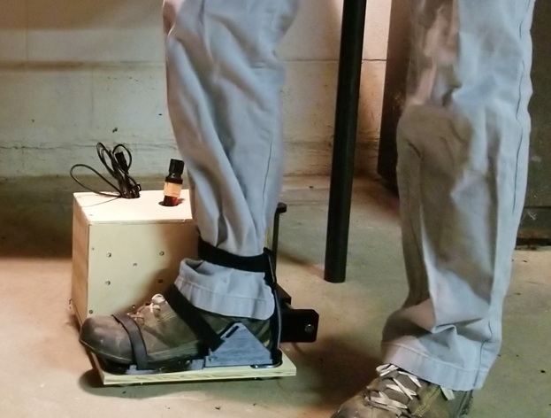
The user can lift his foot while still being coupled to the shoe, as shown in Figure 8.
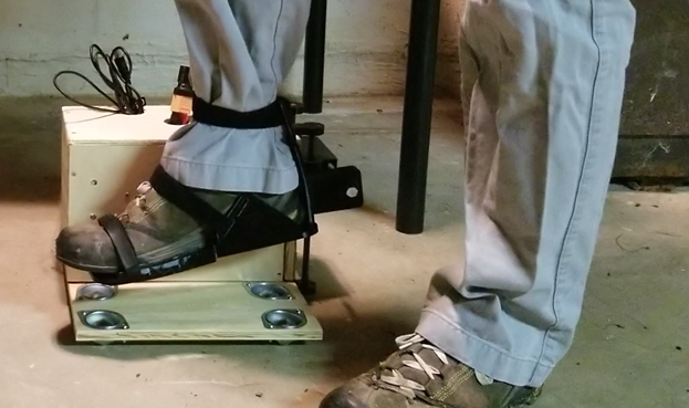
The user remains coupled thanks to the binding the foot is strapped into being connected to the shoe along two rods, as shown in Figure 6 and Figure 8. The binding can move up and down along the rods. This video also shows the motion. The two rods could be substituted for extension slides or rails.
https://i.imgur.com/Qej9s7t.mp4
Walking Explained
Using the binding component, when the user wants to walk in any direction he will first lift his foot like he would normally do when starting to walk. The shoe will roll along the floor as the user lifts his foot in the air. When the user brings his foot back down, the motors will activate to bring the user’s foot back to where it started. This motion is shown in the following video.
https://i.imgur.com/s5AeQ0Y.mp4
Support Structure
A safety harness will be used in this design. The user will secure a safety harness to the ceiling above them (or some support structure above them, such as something like a portable pull up bar). This harness will prevent the user from falling.
Powering the Motorized Shoe
The motorized shoes could be either powered by a battery or a power supply. For a battery, the battery could be part of the motorized shoe or be secured to the user, such as in a belt or backpack. For using a power supply, wires will need to be run along the user up and over the user’s head then to a power supply. This is to support the user turning 360 degrees without the wires wrapping around the user. Above the user’s head, a slip ring can be used to allow the wires to spin 360+ degrees while being connected to the power supply.
Safety Harness Sensor
The tether connecting the safety harness to the ceiling or support structure can include an accelerometer or gyro sensor. This sensor can be used to detect where the user is relative to the center point of the entire assembly. Figure 9 shows where the accelerometer will be.
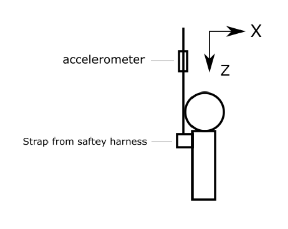
Modern day accelerometer can measure acceleration in 3 or more directions, including the acceleration due to gravity. In the above image, the accelerometer will detect the acceleration due to gravity in the Z direction. The X and Y directions will not feel any acceleration due to gravity. Using the detected acceleration due to gravity, a 3D vector can be constructed. In this case, the X and Y components of the vector are 0, and the Z component is 9.8 (assuming the accelerometer reports acceleration in meters per second per second).
If the user takes a step forward, then the accelerometer will detect this because the Z axis will detect less of a pull due to gravity, and the X direction will start to feel a pull due to gravity, as shown in Figure 10.
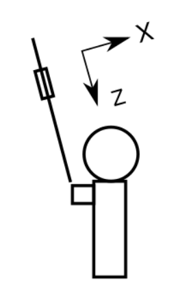
Another 3D vector can be constructed. The X component could be 4 and the Z component could be 7, for example. If the user then takes a step directly left or right (relative to their point of view), the Y component will feel a pull due to gravity. Then the Y component could also be 4, for example. Then the 3D vector will be (4, 4, 7). Using this vector, the direction the user is away from the center point can be measured. The exact distance the user is away from the center point cannot be precisely measured unless the height the accelerometer is from the ground is known, but knowing the exact distance is not necessary.
Sensors will also be placed in the motorized shoes themselves. These sensors will be able to track the speed and direction the motorized shoes are moving in.
Return to Center Algorithm
I’ll now explain how the sensors in the motorized shoes and the sensor attached to the safety harness tether can be used to turn the motors on and off such that the user will constantly be moved back to his starting position as he walks. Please take a look at Figure 11.
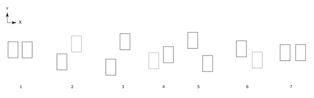
When the rectangle is solid, that means that the user’s foot is on the motorized shoe. When a rectangle is dotted, that signifies that the user’s foot is in the air and the user is bringing the shoe forward (or to the side) along with their foot.
Step 1 is the starting position of the user, where they are standing still, shoulder-width apart. In step 2, the user starts taking a step forward. The right foot is in the air, and the motorized shoe is being brought forward along with the user’s foot. The sensor in the right shoe will detect an acceleration in the positive Y direction. The acceleration in the positive Y direction in the right shoe will trigger the left shoe’s main motor to turn on. The left shoe will be start moving backwards. The velocity that the left shoe will move backwards will be calculated by integrating the acceleration of the right to find the velocity of the right shoe. Then the actual velocity of the left shoe will be found the same way. So the speed of the shoe attached to the foot in the air determines the speed of the shoe attached to the foot on the ground.
In step 3, the user has put their right foot down on the motorized shoe assembly again. In step 4, the user lifts their left foot and begins moving it forward. Just like in step 2, when acceleration is detected in the left shoe, the right shoe is signaled to move backwards.
In step 5, the user has brought their left foot down. Now the user decides to take one last shorter step, and then to stop. The shorter step is shown in step 6. In step 7, when the user brings their right foot down, she does not start to move their left foot. Since she doesn’t move their left foot, no acceleration in the left foot is detected, so the motors in the right foot’s shoe do not start up.
Let’s now imagine that in step 5, instead of the user taking another step forward, she decides to take a step to the side, as shown in figure 12.
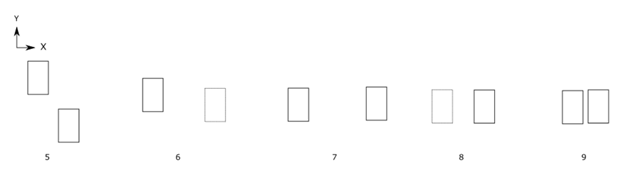
Shown in step 6, the user will lift their right foot and start moving it in the positive X direction. In step 7, the user has put their right foot down. In step 8, she continues their strafing to the right. She brings their left foot up and starts moving it I the positive X direction. Since acceleration in the left shoe is detected, the right shoe will start moving backwards. In step 9, the user brings their left foot down. So to summarize, the direction and speed the user lifts his foot in is detected by the sensor and used to tell the opposite shoe how fast to move and what direction to move in.
The sensor attached to the safety harness tether will be used to correct for slight errors in the above process. In step 9, the user could end up slightly to the right of the center point. The sensor attached to the safety harness will detect this, and can instruct the motors in both shoes to turn on and bring the user to the center.
The algorithm, step by step, is as follows.
- Acceleration in one of the motorized shoes is detected. The sensor in the motorized shoe will detect acceleration along the X and Y axes.
- The velocity in the X and Y directions of the motorized shoe that is moving is extrapolated from the measured acceleration. A 2D velocity vector is constructed using the X and Y velocities.
- The other shoe, which acceleration was not detected in, will have its motors activated so that the motorized shoe starts to move. It will move at the same speed as the other shoe, but in the opposite direction. The velocity of this shoe will be extrapolated from its own acceleration. Once the velocity matches the velocity of the other shoe, speed will be held steady.
- When acceleration in the first motorized shoe stops, the motors in both shoes will be turned off.
- The sensor attached to the tether of the safety harness will detect of the user is some distance away from the center point. The center point is defined as the point where this sensor only measures acceleration due to gravity in the Z direction.
- If the user is at a position such that actuating them would cause the user to be brought back to the center point, then the motors in both shoes will start up to actuate the wheels until the center point is reached.
Interfacing with a Video Game
When the motorized shoes move, the microprocessor can send the speed and direction to a driver on the user’s computer. This driver acts as a typical video game controller driver. The direction and speed that the user is moving in the real world will be communicated to a video game using the driver, so that the user’s avatar in the video game moves in the same direction and at a configured speed. The configured speed in game could, for example, be twice as fast as the user actually moves in the real world.
Possible Design Improvements
Below are some possible design improvements that I am going to consider. I don’t believe any of these improvements are major design changes.
Alternative to Accelerometer Attached to the Safety Harness Tether
Instead of using an accelerometer attached to the safety harness tether to detect when the user is outside of the center point, and then used to actuate the wheels to bring the user back to the center point, I could possibly replace the tether with a strong pole that has a string spring or bungee cord attached to it. The pole can be similar to what previous versions of the Infinadeck had, which you can see here.
If the user leaves the center point, the bungee cord or spring will be decompressed. Then the bungee cord or spring will compress and bring the user back to the center point.
Push Button to Detect When the User Raises and Lowers their Foot
I may find that I need to know when the user raises or lowers their foot. To do this, I can add a push button to the binding so that when the user lifts their foot, the push button is not pressed. When the user lowers their foot, the push button is pressed.
Calibrating the Accelerator Algorithm
I may find that for some people, when they are walking it would feel more natural if the motorized shoe assembly would move the user’s foot back at a slightly different velocity than the velocity of the foot moving forward.
To accomplish this, I can create a separate small device that the user straps onto their shoe. This device will contain an accelerometer or gyro. This device is used separate from all of the other components, meaning she is not strapped into the safety harness or the motorized shoe assembly. When the user activates the device, she can walk forward, backwards, side to side as much as she wants. She should do this in an open area so that she has enough room to walk in every direction. While the user walks, the device will collect the accelerations of the user’s feet. This data can then be used in the algorithm to slightly adjust the speeds at which the motorized shoes move so that it feels more natural for that user.
Crouching Support
Support for detecting when the user crouches, so that the user’s avatar in a video game can crouch, can be easily added by adding a spring or bungee and a push button to the tether that attaches to the safety harness. When the user crotches, the spring/bungee will be decompressed and the push button will be un-pressed. This will signal to the microprocessor that the user has crouched. When the user goes back to a standing position, the spring/bungee will compress and the push button will be pressed, signaling to the microprocessor that the user is now standing.
Jumping Support
Since the user can lift their feet without the whole motorized shoe assembly coming off of the ground, it’s possible that the user could do a small jump. An accelerometer could be added to the binding to detect the rapid acceleration from the jump. When the user jumps, the microprocessor can signal the video game controller driver to tell the user’s avatar in the video game to jump.
It’s likely that to support jumping, shocks would need to be added to the motorized shoe assembly to absorb the impact.
Spacer Rod
To make sure that the user, while strafing, won’t accidently run the motorized shoes into each other, a spacer rod could be connected in-between both shoes, as show in figure 13.
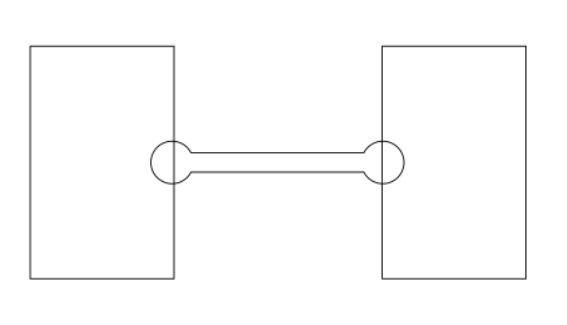
The rod can expand, but has a minimum length. When the user takes a step forward, it would look like Figure 14.
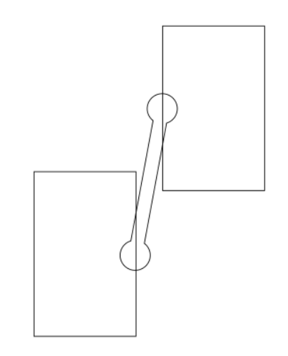
The rod would also provide additional stability and make it virtually impossible to tip the shoes (towards each other) and role an ankle.
Revisions
Created on Sunday November 24, 2019.
Added link to part 2 on April 24, 2020.