In this article I’ll talk about some improvements I made to the wheel hub drive from the last article and some other designs I have tried since then.
The planetary gear I was using used 5 planets. You can see in Figure 1 that the planets are so close together that they actually touch each other. This was causing extra friction so I tried 4 planets instead, shown in Figure 2. This seemed to work better.
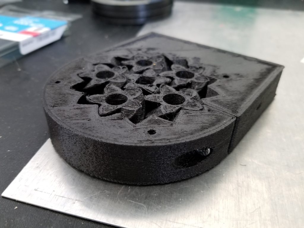
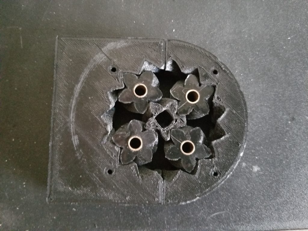
In Figure 2 you can also see that I inserted sleeve bearings. I hoped that the sleeve bearings would help decrease the friction caused by the planets spinning around the bolts that attach them to the Y carriage.
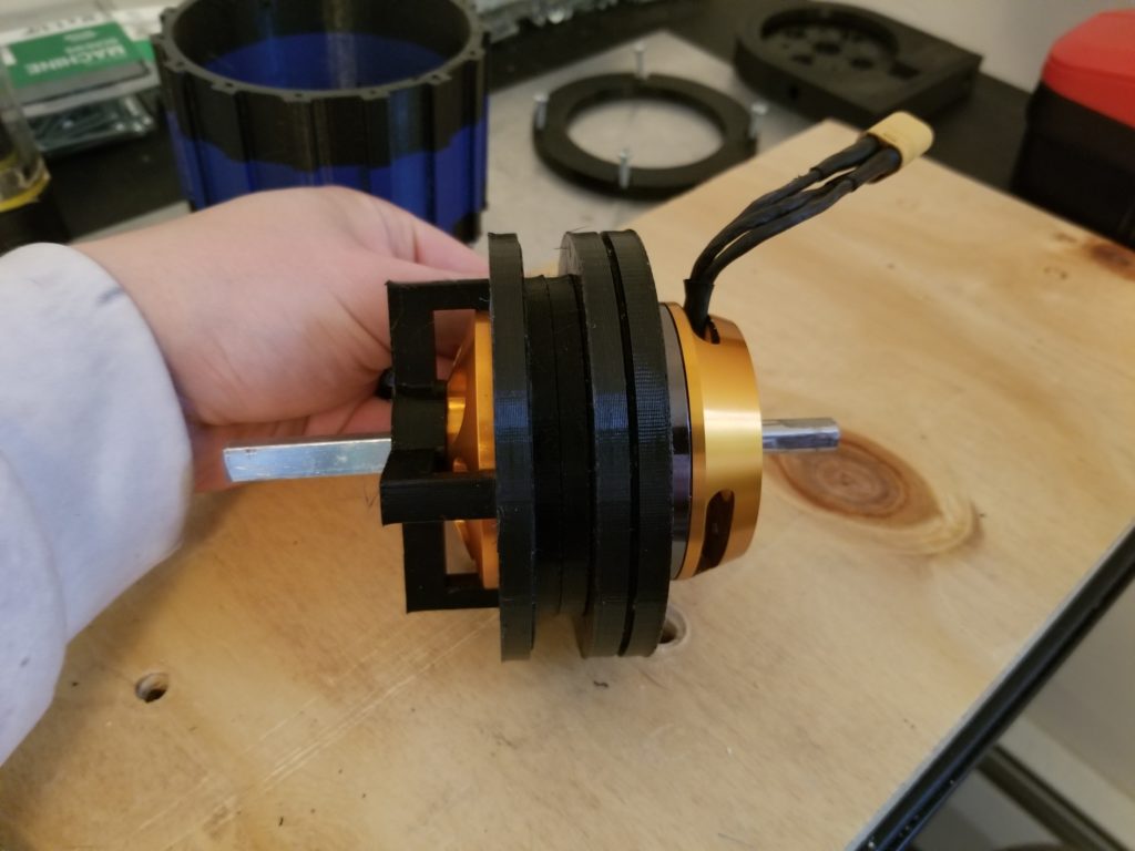
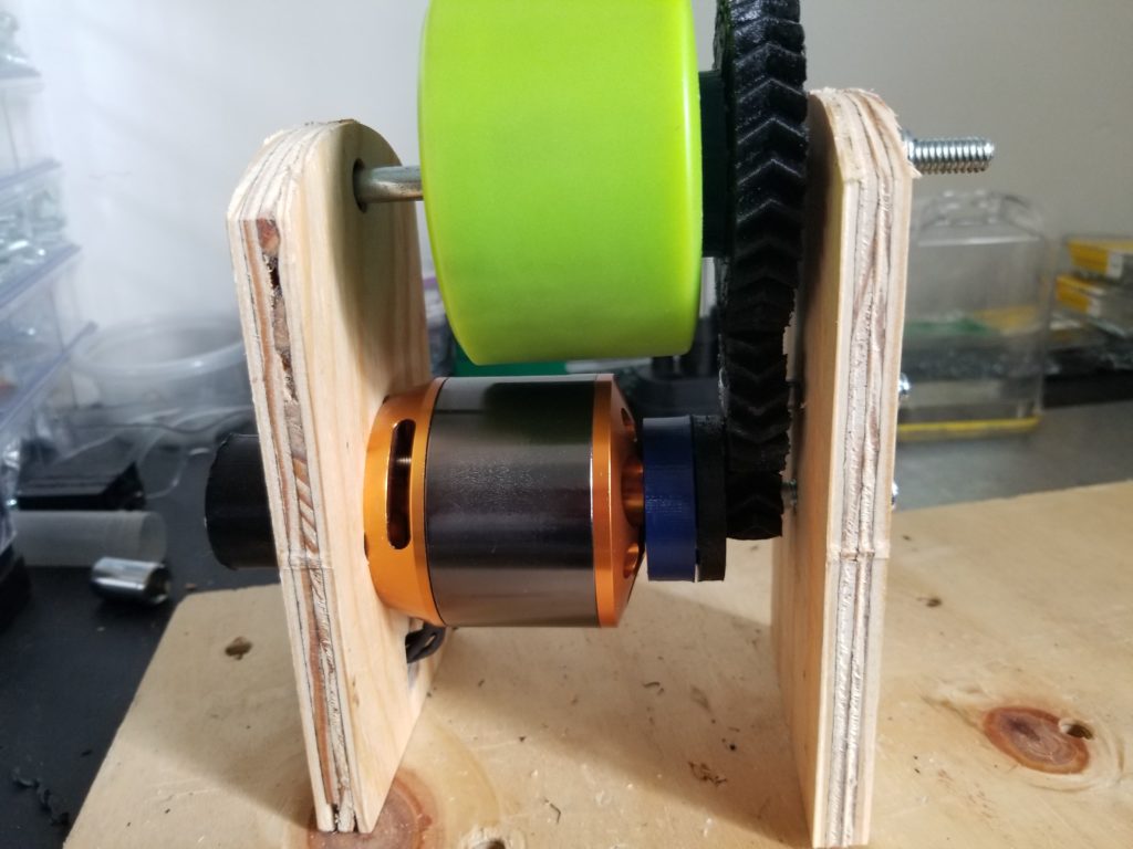
I ended up redoing the rear motor mount, shown in Figure 3. Also shown are the 3D printed bearings I used that go around the motor.
To test the assembly’s strength I tied a rope around it and attached the other end to the ball transfer skateboards I made, as shown in Figure 4.
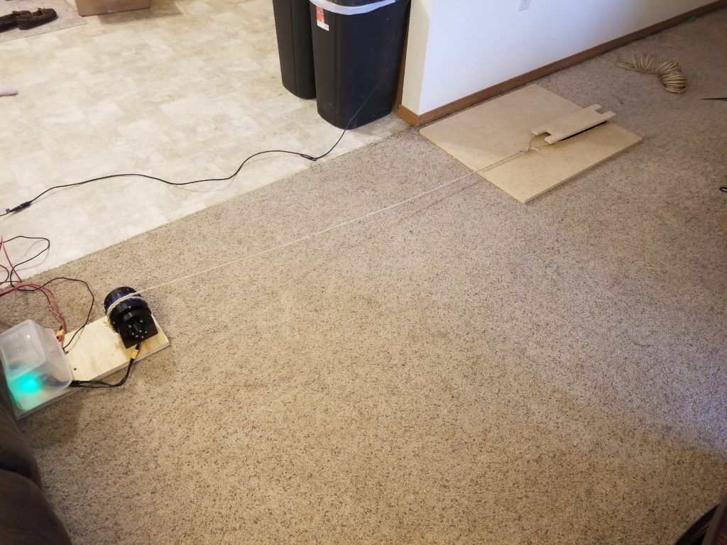
I stepped on the skateboard and turned the motor on to see if it could pull me (I weigh about 160 pounds). The results were disappointing. It was not able to pull me when I stood on the skateboard with the 3D printed ball transfers. It was able to pull me when I stood on the skateboard that had 5 ball transfers I bought from McMaster, but it took a lot of current to do so (I believe around 30 amps).
The planetary gear seemed to not be causing much friction once I went down to 4 planets and put the sleeve bearings in. I thought that maybe the bolts that go through the planets were being pulled to one side when under a heavy load, causing the planets to tilt a little. But after taking a video of the planets under load it looked like they were not being tilted.
I believe the problem is mainly with the 3D printed bearings shown in Figure 3 and discussed in part 1. I don’t think they can handle the load I’m trying to put them under. Since there is only one ring of BBs, and the motor and hub spin at different rates, the BBs probably do more sliding than rolling, causing friction. I may have to redesign the bearings to have 2 rings of BBs, one for spinning with the motor and one for spinning with the hub. The plastic parts may also flex under high load, causing more friction.
Other Motor Drive Designs
I created a few more designs that I hoped would be able to handle heavy loads. These designs focused on minimizing friction. The first is shown in Figure 5.
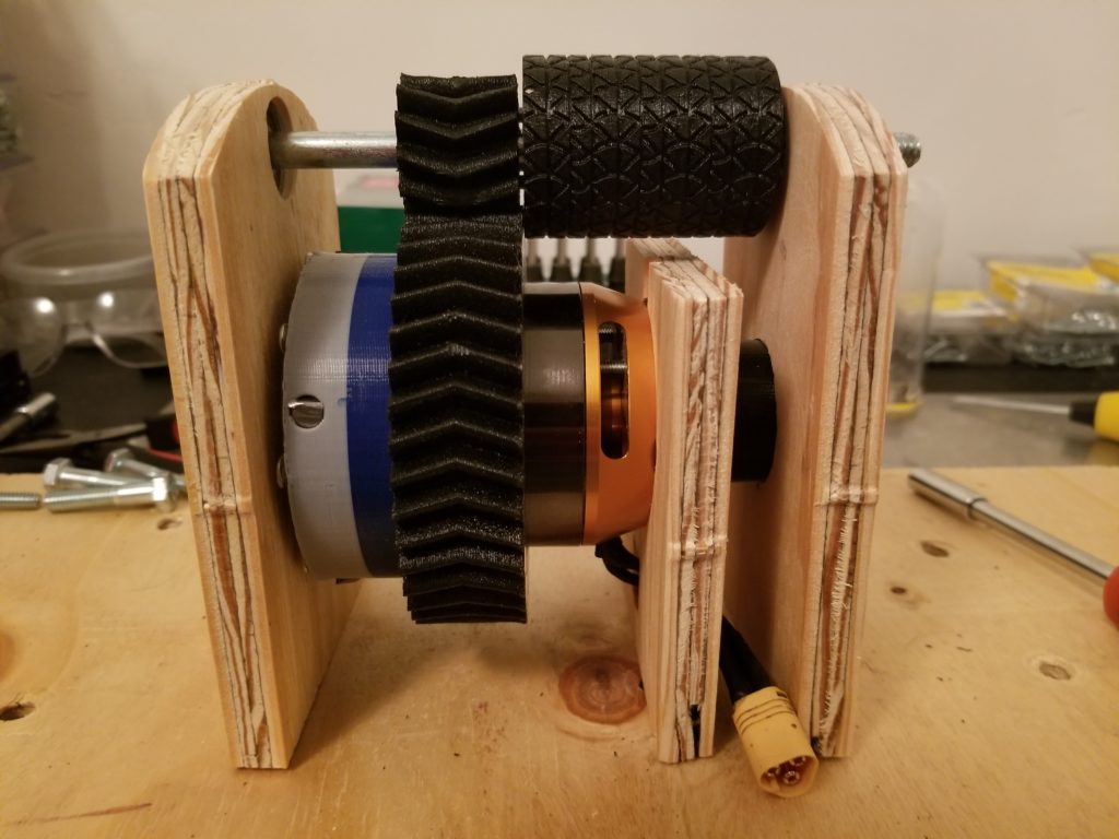
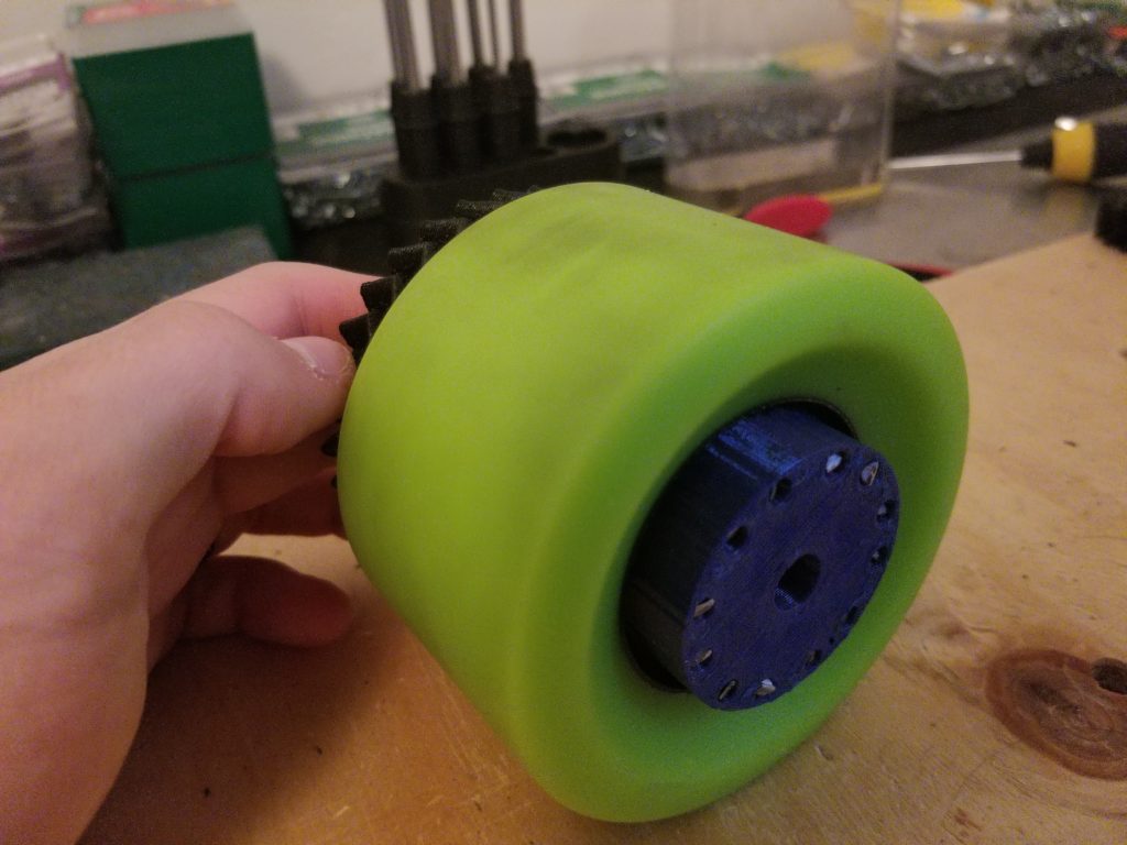
This design drives a smaller wheel. I wanted to see if the motor could provide the torque needed to rotate the large gear I slid around it. I cut out the wood pieces on my CNC. The wheel was printed out of TPU and attached to the gear via 1/8″ steel rods, as shown in Figure 6 and 7. The tire tread was copied from here.
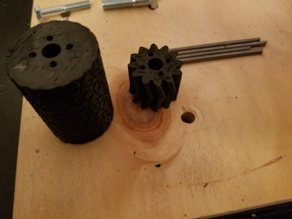
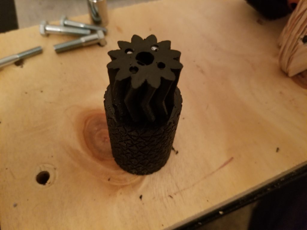
Figure 7: Wheel, gear, and 1/8″ steel rods assembled
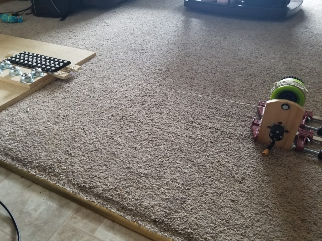
I performed the same kind of load test as before, shown in Figure 8.
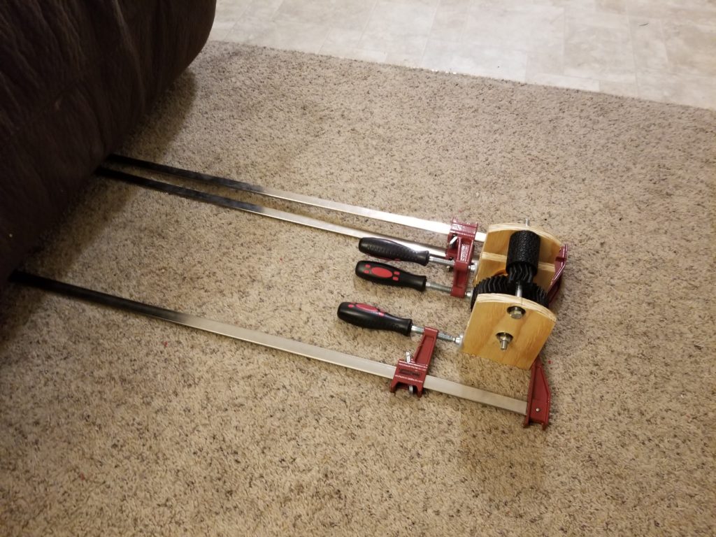
Disappointingly, the this motor drive was not able to pull me either, even when I used the skateboard that used the ball transfers I bought from McMaster.
The last design I tried is shown in Figure 9.
This design used a simple gear train to get a gearing ratio of 4:1 between the motor and the longboard wheel. The wheel was attached to the gear using 1/8″ steel rods like the last design, as shown in Figures 10 and 11.

This design was tested like the others, as shown in Figure 12.
This design actually worked! It was able to pull me when I put all my weight on both of the skateboards shown in Figure 12. The current it took to pull me is shown in Figures 13 and 14.
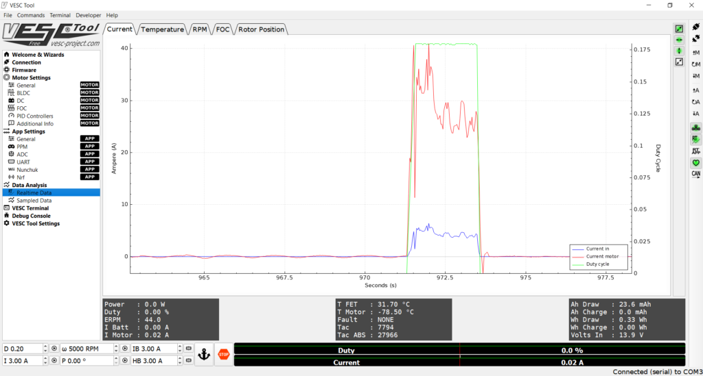
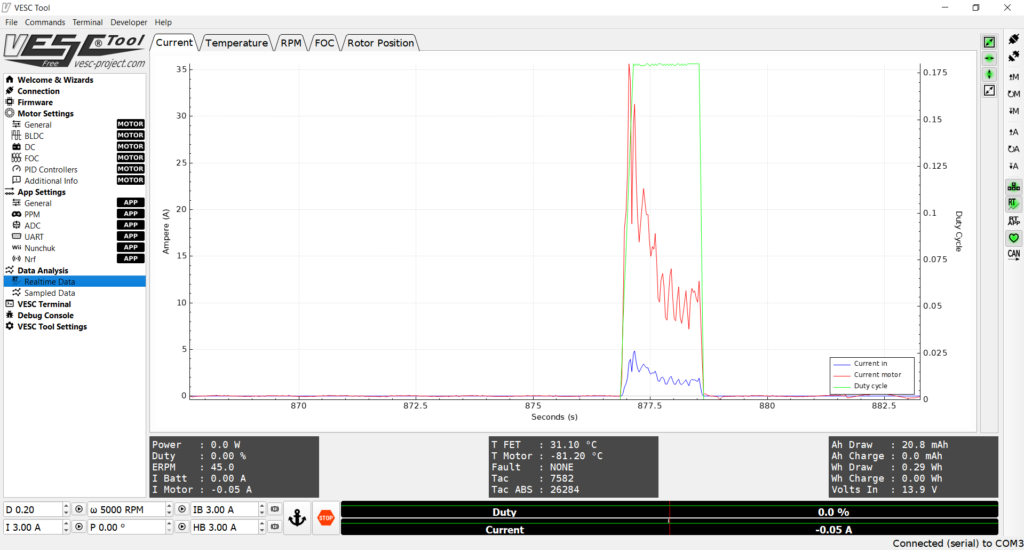
Figure 13: Current draw when the gear train design pulled my weight while I stood on the skateboard using the ball transfers I bought from McMaster
You can see that the ball transfers from McMaster used less current. It takes more force to start pulling a load from a dead stop than to keep it going, so I believe that’s why the current is highest in the beginning (and the startup boost may be too high).
Conclusion
I’m going to move forward with the gear train design. I’ll improve the design in several ways. For example, I’ll try to redesign it so that the middle gear is supported on both sides and I’ll probably make the gears thicker.